Understanding Direct Current (DC) Circuit Theory: A Comprehensive Guide
DIRECT CURRENT (DC) CIRCUIT
DEFINITIONS
Electric Current (I)
Electromotive Force (E)
Resistance (R)
Conductor
A conductor is a material that readily allows the flow of electric current (charge) through it. Conductors have very low resistance to the flow of electric current. Examples are copper, aluminum, iron, silver etc.
Electrolyte
It is a substance whose aqueous solution conducts electric current. Examples are salts (sodium chloride), Potassium Carbonate acids (hydrochloric acid, tetraoxosulphate (v) acid and bases (copper oxide, sodium hydroxide).
Insulator
An insulator is a material that does not allow the flow of electric current through them. Insulators have high resistance to the flow of electric current. Examples are glass, plastics, porcelain, dry wood, polythene, ebonite, etc.
Semiconductor
Sources of Energy
Cell: A cell is a device that converts chemical energy into electrical energy. There are two basic sources of electrical energy.
Secondary Cells: They produce direct current and voltage and can be recharged when discharged. Examples are lead acid accumulator, electric bell etc.
Resistors
TYPES OF RESISTORS
(1) Carbon
(2) Wire wound
(3) Variable
THE STANDARD COLOR CODE
Resistor values are often indicated with color codes. The code is given by several bands. Together they specify the resistance value, the tolerance and sometimes the reliability or failure rate.
Resistors color code is a system of identifying resistors by painting or coloring its bands. The resistance value, tolerance and wattage rating are generally printed on the resistors as numbers or letters. But when the resistors are small (e.g. 1/4W, 1/2W etc.), these specifications must be shown in some manner as the print would be small to read. Therefore, small resistors use color printed bands to indicate both their resistive value and their tolerance with the physical size of the resistor indicating its wattage rating.
THE STANDARD COLOR CODE
|
COLOR |
BAND A 1ST NUMBER |
BAND B 2ND NUMBER |
BAND C NUMBER OF NOUGHT |
BAND D TOLERANCE |
|
BLACK |
0
|
0
|
0
|
-
|
|
BROWN |
1
|
1
|
1
|
1%
|
|
RED |
2
|
2
|
2
|
2%
|
|
ORANGE |
3
|
3
|
3
|
-
|
|
YELLOW |
4
|
4
|
4
|
-
|
|
GREEN |
5
|
5
|
5
|
-
|
|
BLUE |
6
|
6
|
6
|
-
|
|
VIOLET |
7
|
7
|
7
|
-
|
|
GREY |
8
|
8
|
-
|
-
|
|
WHITE |
9
|
9 |
-
|
-
|
|
SILVER |
-
|
-
|
÷100
|
10%
|
|
NON |
-
|
-
|
-
|
20%
|
|
PINK |
-
|
-
|
-
|
|
|
GOLD |
-
|
-
|
÷10
|
5%
|
Numerical Example
1. A resistor is coded, yellow, violet, red and gold. Determine the value of
the resistor.
Solution
Yellow = 4, Violet = 7, R = 2, Gold = 5%
= 4700 + 5%
= 4700 × 5⁄100
= 235Ω
Upper value = 4700 + 235 = 4935Ω = 4.935KΩ
Lower value = 4700 – 235 = 4465Ω = 4.465KΩ
Tolerance ranges from 4.465KΩ - 4.935kΩ
2. A resistor is coded green, blue, brown and silver. Determine the value of
the resistor.
Solution
Green = 5, Blue = 6, Brown = 1
Silver = 10%
560 ± 10%
560 × 10⁄100
= 56Ω
Upper limit = 560 + 56 = 618Ω
= 0.616KΩ
Lower limit = 560 – 56 = 504Ω
= 0.504KΩ
Ranges from 504Ω - 616Ω.
3. A resistor marked with color bands red, violet,
orange and gold has the value of? (NOVDEC. 2005 Objective Question 30)
Solution
R = 2, Violet = 7, Orange = 3, Gold = 5% = 27000 ± 5%
= 27000 ×5⁄100 = 2,70k KΩ
4. The resistance of 650 resistor of a tolerance of 10%
ranges from? (SSCE May/June 2011 Objective Question 57)
Solution
Blue = 6, Green = 5, Brown = 0
= 650 ± 10%
650 ×10⁄100= 65 Ω
Upper limit = 650 + 65 = 715Ω
Lower limit = 650 – 65 = 585Ω
Ranges from 585Ω - 715Ω
Types of Resistors Connections
1. Series connection
2. Parallel connection
3. Series-Parallel Connection
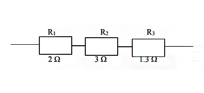
Series Connection
A resistor is said to be connected in series when the same current flows through each resistor. It implies that the resistors are connected on the same wire (conductor).
The total (equivalent or effective) resistance is greater than the value of the highest individual resistance in the circuit.
In series resistors, current is the same
I = I1 + I2 + I3
Sum of Voltage drops equal the supply Voltage
V = V1 +V2 +V3
V1
= IR1, V2
= IR2, V3
= IR3
From Ohm’s Law
V = IR
V = IR1 + IR2 + IR3
IR = IR1 + IR2 + IR3
Dividing through by I
R = R1 + R2 + R3
Example
Calculate the total resistance in the circuit above.
Solution
RT = R1 + R2 +R3
+ R4
=
(2+1+3+4) Ω
= 10 Ω
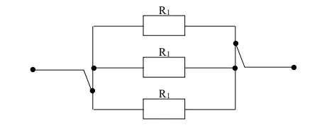
Parallel Connection
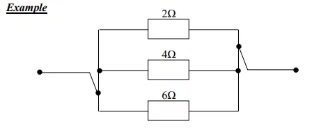
A resistor is said to be connected in parallel with one another when the same voltage appears across each resistor.
The total (equivalent or effective) resistance is less than the value of lowest individual resistance in the circuit.
In
parallel circuit, Voltage is the same
V = V1
= V 2 = V3
Sum of currents through each component equal the
supply current
I = I1
+ I2 + I3
From Ohm’s Law
I = V/R
I1 =
V/R1, I2 =
V/R2, I3 = V/R3
I = V/R1 + V/R2 + V/R3
V/R = V/R1 + V/R2 + V/R3
Multiplying through by 1/V
1/R = 1/R1 + 1/R2 + 1/R3
Solution
1/RT =
1/R1 + 1/R2
+ 1/R3
= 1/2 + 2/4 + 3/6
= (6 + 3 +
1)/12
1/RT = 10/12
RT = 12/10 = 1.2 Ω
Further Reading: Parallel Circuits
Series – Parallel Connection
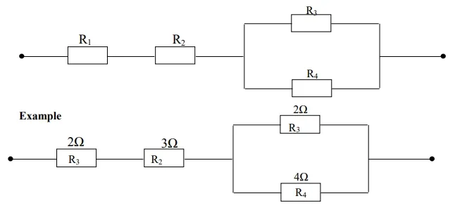
Resistors are said to be connected in series-parallel when the same current flows through the series resistors and the same voltage appears across the parallel resistor.
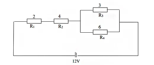
Calculate the total resistance in the diagram above.
Solution
Finding the Total Resistance in Parallel
Given:
The formula for calculating the total resistance in a parallel circuit is:
Plugging in the values:
To add the fractions, find a common denominator:
Now, take the reciprocal to find
So, the total resistance is:
Alternatively
Given:
The formula to find the equivalent resistance in a parallel circuit is:
Plugging in the values:
Calculating the product:
Now, add the resistances in the denominator:
Finally, simplify the fraction:
So, the equivalent resistance for the parallel connection of resistors 2 Ω and 4 Ω is approximately 1.33 Ω.
𝑅𝑇 = 𝑅1 + 𝑅2 + 𝑅𝑃
= 2 + 3 + 1.3
= 6.3Ω
Quantity of Electricity
Quantity of electricity is defined as the quantity of electric current passing through a given point in a circuit in a length of time. It is measured in coulombs (c).
Quantity of electricity = Current x time
Q = It
Q = Quantity of electricity (coulombs)
I = Current (Ampere)
T= Time interval (Seconds)
Numerical Example
1. The current flowing in a circuit is 2A. Calculate the quantity of electricity in the circuit in a time interval of 40 seconds.
Solution
Current (I) = 2A
Time (t) = 40 seconds
Quantity of electricity (Q) = ?
Q= It
= 2 × 40
= 80c
2. A current of 20mA flows for 2hrs through a circuit. Calculate the quantity of electricity passing through the circuit.
Solution
Current (I) = 20mA = 20X10-3 = 20/1000 = 0.02
Time (t) = 2hs = 60s = 1m, 60m = 1hr, 120m = 2hrs,
therefore 120X60 = 7200s
Q = It
= 0.02 X7200
= 144c
1. A current of 120mA flows for 3hrs through a circuit. Calculate the frequency of electricity passing through the circuit.
2. The current flowing in a circuit is 6A. Calculate the time intervals in seconds if the quantity of electricity in the circuit is 240c.
3. Calculate the current flowing in a circuit if the quantity of electricity in the circuit is 80c in a time interval of 40 seconds.
{nextPage}
OHM’S LAW
Ohm’s law states that the current flowing through a metallic conductor is directly proportional to the potential difference (voltage) provided temperature is kept constant.
I α V/R → I = KV/R
I = V/R
V = IR
NUMERICAL EXAMPLE
A torch has 6V battery and a bulb of resistance of 12Ω. Calculate the current flowing through the bulb when the switch is closed.
Solution
Voltage (V) = 6V
Resistance (R) = 12Ω Current (I) =?
From ohm’s law,
I = 5/12
I = 0.5A
Power and Energy in DC Circuits
Electrical Power
Power is defined as the rate of dissipating energy.
The unit of power is the watts (W) and measured using a wattmeter.
P = I2 R, P = I V ,
The energy (W) consumed over time (t) is given by:
Where is measured in joules (J), in watts (W), in volts (V), in amperes (A), and in seconds (s).
Further Reading: Power in Electrical Circuits
Electrical Energy
Electrical energy is defined as the consumption of
power in a length of time. It is measured in joules (J).
E =
Power × Time
E = I2Rt, E
= IVt , E = V2t/R
Numerical Example
(1) A cell of emf 5V is connected to a circuit of resistance 8Ω. Calculate;
(a) The current in the circuit
(b) The power consumed by the circuit
(c)The energy consumed if the emf is connected for 22min
Solution
Voltage (V) = 5V
Resistance (R) = 8Ω
Time (t) = 22min
(a) Current (I) = V/R = 5 /8
I = 0.625A
(b) P = IV = 0.625 X 5
P = 3.125 W
(c) Energy (E) = 𝑃𝑜𝑤𝑒𝑟 × 𝑡𝑖𝑚𝑒
E = I2Rt,
But 1minute = 60seconds, 22minutes = (22x60)/1
= 1320s
= 0.625 × 0.625 × 8 × 1320
= 41255J
(2) A student leaves an electric iron on for a period
of 8hours. If the iron has 2KW element, calculate the energy consumed in;
(a) Joules
(b) KJ
(c) KWh
Solution
Power (P) = 2KW =2000W
Time (t) = 8H
= 8 × 3600s = 28800s
Energy (E) =?
(a) E = Power × time
E = 2000 × 28800
E = 57600000J
(b) E = 57600000/1000
E = 57600KJ
(c) E = Power (KW)
× time (h)
E = 2KW × 8h
E = 16KWh
From the circuit above, calculate the;
(a) Effective resistance in the circuit
(b) Total current in the circuit
(c)Current in the 6Ω resistor
(d) Current in the 3Ω resistor
(e) Power in the 2Ω resistor
(f) Energy consumed by 4Ω resistor
If the circuit was on for 10 minutes
Solution
Parallel
Given:
The formula for the total resistance in parallel is:
Plugging in the values:
To add these fractions, find a common denominator:
Taking the reciprocal to find :
So, the equivalent resistance is:
In Series connection
Given:
The formula for total resistance in series is:
Calculating:
So, the total resistance is 8 Ω.
Total Current Calculation
To find the total current , use Ohm's Law:
Given:
- Voltage
Plugging in the values:
So, the total current in the circuit is 1.5 A.
(b) Current in the 6Ω resistor Using current divides rule
Where:
- is the total current through the parallel combination.
- (total current from the series circuit)
Plugging in the values:
Calculate the denominator:
So:
Simplify:
So, the current through is 0.5 A.
(c)
Current in the 3Ω resistor
The formula to find the current through a resistor in a parallel circuit is:
Where:
- is the total current through the parallel combination.
- (total current from the series circuit)
Plugging in the values:
Calculate the denominator:
So:
Simplify:
So, the current through is 1 A
(d) P𝑅2 = (𝐼𝑇)2 ×𝑅2
= (1.5)2 × 2
= 2.5 × 2 = 4.5𝑊
(e)
Energy in 4Ω resistor in 10 minutes
10
minutes = 10 x 60 = 600s
𝐸
= 𝐼2𝑅4 × 𝑅4 × 𝑡
= (1.5)2 × 6 × 600
= 2.25
× 4 × 600
= 900J
{nextPage}
Resistivity and Conductivity
Resistivity: Resistivity of a material is the ability of the material to oppose/regulate the amount of current flowing through the material. Resistivity is the reciprocal of conductivity. Low resistivity relates the materials having low opposition to the flow of current. The resistance of a material depends on;
(a) The resistivity of the material (p) (Ωm)
(b) The length of the material (l) (m)
(c) The cross – sectional area of the material (𝑚2)
Numerical Example
(1)A copper wire has a length of 200m and a cross – sectional area of 0.2 × 10⁻⁶𝑚2. Calculate the;
Resistance of the material if the resistivity of copper is 1.73 × 10⁻⁸Ω𝑚.
Solution
Length (L) = 200m
Area (a) = 0.2
× 10−6𝑚2
Resistivity (p) =
1.73 × 10⁻⁸Ω𝑚
Resistance (R) =
?
R = 𝓅𝑙 /𝑎
Step-by-Step Calculation
- Calculate the Numerator:
- Calculate the Denominator:
- Divide the Numerator by the Denominator:
To simplify:
= 1730 × 10−2 = 17.3Ω
(2) Calculate the resistance of 300m length of copper
wire of diameter 1 mm whose resistivity is
1.73 × 10⁻⁸ Ωm
Solution
Length (l) = 300m
Resistivity ( = 1.73 × 10⁻⁸ Ωm
Diameter (d) =
1mm = 1 × 10⁻³
Area of conductor (a) = ?
Where:
Step-by-Step Calculation
- Square the Diameter:
- Calculate the Numerator:
- Divide by 4:
Result
The area is:
R = 𝓅𝑙 /𝑎
= (1.73 × 10−8 x 300)/( 0.7855 x 10⁻⁶) = (51.9 x 10⁻⁸)/(0.7855 x 10-6 )
= 660.726 x 10-2
= 6.61Ω
Conductivity: Conductivity is the ability of a material to allow the free passing of electric current through it. The symbol for conductivity is (ϭ) sigma.
ϭ = 1/𝓅(Ωm)-1
Conductance: Conductance is the reciprocal of resistance of a material. The symbol is G.G = 1/R Siemens (S)
Numerical Example
(1) A copper wire has
a resistance of 10Ω. Determine its conductance.
Solution
Resistance (R) = 10Ω
Conductance (G) =?
G =1/R = 1/10 = 0.15S
(2) A copper wire has
a conductance of 0.2 Siemens. What is
the resistance of the wire?
Solution
Conductance (G) = 0.2S
Resistance (R) =?
R =1/G
= 1/0.2 = 5Ω
(3) A copper wire of length 50m has a conductance of 5
Siemens. Calculate the area of the conductor if the resistivity of copper is
0.0173Ωm. (Take 𝓅 = 0.0173µΩm)
Solution
Given Data
- Length of the wire () = 50 meters
- Conductance () = 5 Siemens
- Resistivity of copper () = 0.0173 µΩ·m
First, convert resistivity to Ω·m:
Steps to Calculate the Area
- Calculate the Resistance () from Conductance:
Thus:
Plugging in the given conductance:
- Use the Formula for Resistance:
The formula for resistance is:
Rearrange to solve for :
- Plug in the Values:
Substitute these into the formula:
- Calculate:
Result
The cross-sectional area of the copper wire is:
TEMPERATURE COEFFICIENT
A temperature coefficient describes the relative change of a physical property that is associated with a given change in temperature.
The resistance of most materials changes with temperature. In general, conductors increase their resistance as the temperature increases and insulators decrease their resistance with a temperature increase.
Therefore, an increase in temperature has a bad effect upon the electrical properties of a material. Each material responds to temperature change in a different way, and constants have been calculated for each material (temperature coefficient of resistance ∝).
Temperature coefficient values
|
Material |
Temperature coefficient (
Ω/ Ω oС) |
|
Silver |
0.004 |
|
Copper |
0.004 |
|
Aluminium |
0.004 |
|
Brass |
0.001 |
|
Iron |
0.006 |
|
Carbon |
-0.00048 |
|
Tin |
0.0044 |
For a temperature increase from 0 oС
Rt = Ro (1 + ∝t) (Ω)
Where
Rt = the resistance at the new temperature t oС
Ro = the resistance at 0 oС
∝ = the temperature coefficient for a particular material
For a temperature increase between two intermediate temperatures above 0 oС
R1/R2 = (1 + ∝t1)/(1 + ∝t2)
Numerical Example
(1) The field winding of a D.C. motor has a resistance of 100Ω at 0 oС. Determine the resistance of the coil at 20 oС if the temperature coefficient is 0.004 Ω/ Ω oС.
Solution
Ro = 100Ω , t = 20 oС , ∝ = 0.004 Ω/ Ω oС
Rt = Ro (1 + ∝t)(Ω)
Rt = 100 Ω (1 + 0.004 Ω/ Ω oС × 20 oС)
Rt = 100 Ω (1 + 0.08)
Rt = 108Ω
(2) The field winding of a generator has a resistance of 150Ω at an ambient temperature of 20 oС. After running for some time, the mean temperature of the generator rises to 45 oС. Calculate the resistance of the winding at the higher temperature if the temperature coefficient of resistance is 0.004 Ω/ Ω oС.
Solution
Given Data
- Initial resistance () = 150 Ω
- Initial temperature () = 20°C
- Final temperature () = 45°C
- Temperature coefficient of resistance () = 0.004 Ω/Ω°C
Formula
The formula to calculate the resistance at the new temperature is:
Where:
- is the resistance at the higher temperature.
- is the initial resistance.
- is the temperature coefficient of resistance.
- is the initial temperature.
Calculation
- Calculate the Change in Temperature:
- Substitute Values into the Formula:
- Perform the Calculation:
Result
The resistance of the winding at the higher temperature of 45°C is:
APPLICATIONS OF TEMPERATURE COEFFICIENT OF RESISTANCE
(1) Positive Temperature Coefficient (PTC) Thermistors
(2) Negative Temperature Coefficient (PTC) Thermistors
(3) Heaters
{nextPage}
KIRCHHOFF’S LAWS
The laws were proposed by a German physicist called Gustav Robert Kirchhoff (1824-1887) Junction/Node: A junction or node is point at which two or more conductors meet.
Kirchhoff’s First Law (Current Law)
Kirchhoff’s first law states that the total current flowing towards a junction (node) in a circuit is equal to the total current flowing away from it.
Implication of the First Law
Current cannot accumulate within a circuit.
Total current flowing towards the node N = 𝐼3
+ I4
Total current flowing away from the node
𝑁
=𝐼1
+𝐼2
Therefore; 𝐼1 + 𝐼2
= 𝐼3 + 𝐼4
∑ 𝐼1 +I2 = ∑ 𝐼3 + 𝐼4
(∑ 𝐼1 + I2)
– (∑ 𝐼3 + 𝐼4) = 0
Algebraic sum of currents is zero.
Kirchhoff’s Second Law (Voltage Law)
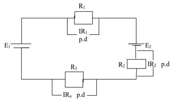
Kirchhoff’s second law states that in any closed circuit, the algebraic sum of the potential drops and emf’s is zero.
Implication of the Second Law
The sum of emfs + sum of pds = 0
∑(𝑒𝑚𝑓𝑠)
+ ∑(𝑝𝑑𝑠) = 0
𝐸1
− 𝐸2 = 𝐼𝑅1 + 𝐼𝑅2
+ 𝐼𝑅3
Numerical Example
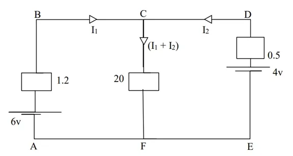
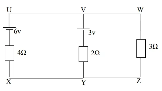
(1) Use Kirchhoff’s laws to calculate for;
(a) The current through each battery
(b) The power
dissipated in the 20Ω resistor
(c)
The terminal voltage.
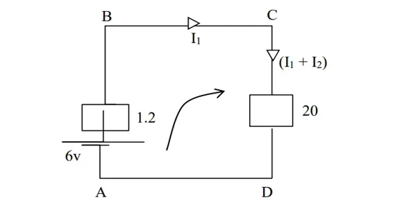
6 =
1.2𝐼1 + 20(𝐼1 + 𝐼2)
6 =
1.2𝐼1 + 20𝐼1 + 20𝐼2
6 =
21.2𝐼1 + 20𝐼2 → (1)
Moving
clockwise
Consider
loop ABDEA
6 − 4
= 1.2𝐼1 − 0.5𝐼2
2 =
1.2𝐼1 − 0.5𝐼2 → (1)
Matching
both equation
6 =
21.2𝐼1 + 20𝐼2 → (1)
2 =
1.2𝐼1 − 0.5𝐼2 → (2)
Equation (1) × 0.5 and Equation (2) × 20
3 =
10.6𝐼1 + 10𝐼2 → (3)
40 =
24𝐼1 + 10𝐼2 → (4)
Add
equation (3) and (4)
43 = 34.6𝐼1
34.6 34.6
𝐼1
= 1.243𝐴
𝑃𝑢𝑡
𝐼1 = 1.243 𝑖𝑛𝑡𝑜 Equation (1)
6 = 21.2𝐼1 + 20𝐼2 Equation (1)
6 = 21.2(1.243) +
20𝐼2
6 = 26.378 + 20𝐼2
6 − 26.378 + 20𝐼2
(−20.378)/20 = 20𝐼2
𝐼2 =-1.018A (It means the cell should be reversed)
(a) 𝐼1 + 𝐼2 = (1.243) + (−1.018) = 10.225A
(b) Power dissipated in the 20Ω resistor
𝑃
= 𝐼2𝑅
𝑃
= (𝐼1 + 𝐼2)2 × 𝑅2
0.2252 × 20
= 1.013W
(c)The terminal voltage
𝑉𝑡
= 𝐸1 − 𝐼1𝑅1
= 6
− (1.243 × 1.2)
= 6
− (1.4916)
= 4.51𝑉
Alternatively
Terminal voltage = (𝐼1 + 𝐼2) × 𝑅(1 + 2)
=
0.225 × 20
= 4.5𝑉
(2) Use Kirchhoff’s laws to calculate for;
(a) The current flowing through each branch of the network
(b) The power dissipated in the 5Ω resistor
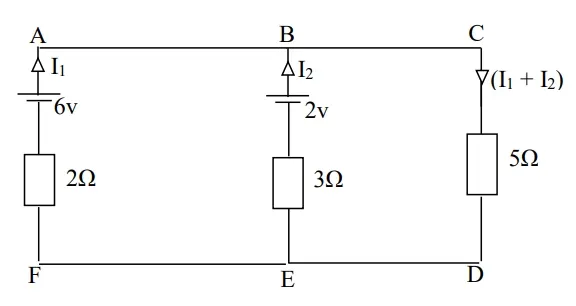
(c)The terminal voltage
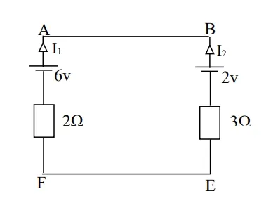
Consider loop ABEFA moving clockwise
6 − 2 = 2𝐼1 − 3𝐼2
4 = 2𝐼1 − 3𝐼2 ………………………… (1)
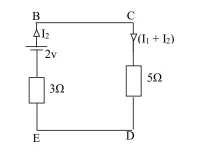
Consider loop BCDEB moving clockwise
2 =
3𝐼2 + 5(𝐼1 + 𝐼2)
2 =
3𝐼2 + 5𝐼1 + 5𝐼2
2 =
8𝐼2 + 5𝐼1
2 = +5𝐼1 + 8𝐼2 ………………………… (2)
Matching equation (1) and (2)
4 =
2𝐼1 + 3𝐼2 ………………………… (1)
2 =
5𝐼1 + 8𝐼2 ………………………… (2)
equation (1) × 8
equation (2) × 3
32
= 216 + 24𝐼2 ………………………… (3)
6 =
215 + 24𝐼2 ………………………… (4)
equation (3) + (4)
38/31 = (31𝐼1)/31
𝐼1 = 1.226 𝐴
𝑃𝑢𝑡𝑡𝑖𝑛𝑔 𝐼 = 1.226 𝑖𝑛𝑡𝑜 equation ( 2 )
2 = 5 𝐼1 + 8𝐼2
2 = 5(1.226) + 8𝐼2
2 = 6.13 + 8𝐼2
2 − 6.13 = 8𝐼2
−4.13 = 8𝐼2
8 8
𝐼2 = −0.5163𝐴
𝐼1 + 𝐼2 = (1.226) +
(−0.513)
= 0.7098A
(b) Power
dissipated in 5resistor
𝑃 = 𝐼2𝑅
𝑃 = (𝐼1 + 𝐼2 )2 ×
5
𝑃 = 0.5038 × 5
𝑃 = 2.19𝑊
(c)The terminal
voltage
= (𝐼1 + 𝐼2 × 𝑅(1 + 2))
= 0.7098 × 5
= 3.549𝑉
Alternatively
= 𝐸2 − 𝐼2𝑅2
= 2 − (0.5163) × 3
= 2 + 1.5489
= 3.5489V
Further Reading: Kirchhoff's Circuit Laws
Trial Test
1.
A p.d. of 5V is maintained across a resistance of 0.8Ω.
Calculate the current flowing through the resistor.
2.
An electric heater has a rating of 2KW at 250V supply.
Calculate the
(a)
current drawn by the heater
(b) resistance of the
heating element
3.
Calculate the resistance of 100 metres of aluminium cable of
1.5mm2 cross-sectional area if the resistivity of aluminium is taken as 28.5 10-9 Ωm.
4.
A coil of copper wire has a resistance 200Ω when its mean
temperature is 0 oС. Calculate the resistance of the coil when its
mean temperature is 80 oС.
5.
The field winding of a generator has a resistance of 10Ω at
an ambient temperature of 20 oС. After running for some time the
mean temperature of the generator rises to 33.4
oС. Calculate the
resistance of the winding at the higher temperature if the temperature
coefficient of resistance is 0.004 Ω/ Ω oС.
6.
State Kirchhoff’s laws
7.
Use Kirchhoff’s laws to calculate for
(a) The current
flowing through each branch of the network
(b) The power dissipated in
resistor.
(c)The terminal voltage
Applications of DC Circuits
DC circuits are widely used in various applications, including:
- Battery-Powered Devices: Many portable electronics, such as smartphones and laptops, operate on DC power supplied by batteries.
- Solar Power Systems: Solar panels generate DC electricity, which is used directly or converted to AC for broader applications.
- Automotive Systems: Vehicles use DC circuits for lighting, ignition, and control systems.
Conclusion
DC circuit theory is fundamental to understanding the behavior and operation of electrical circuits where current flows in a single direction. By mastering the concepts of voltage, current, resistance, and the rules governing series and parallel circuits, one can analyze and design DC electrical systems effectively.
Related Topics on Applied Electricity
- Emission of Electrons and Thermionic Devices
- Data Communication
- Digital Electronics
- Magnetic Field
- Electromagnetism
- Electric Field
- Direct Current Circuit Theory
- Applied Electricity Concise Notes for Senior High Schools (SHS 1, 2 & SHS 3)
- Careers in Applied Electricity
- Common Electrical Devices and Their Uses
- The Impact of Applied Electricity on Modern Technology


.webp)

